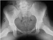
HIP AXIAL PROJECTION
Axial • Craniocaudal View • Complete Evaluation of Pelvis and Joints
AXIAL PROJECTION
Projection providing a longitudinal axis view of pelvic structures

Exposure Factors
Equipment: With bucky. Position: Supine.
Plate Size
Visible Anatomical Structures
Bony Pelvis
Complete
Both Hips
Coxofemoral joints
Proximal Femurs
Both femurs
Iliac Crests
Superior and inferior
Femoral Head
Femur head
- Acetabular rim - Complete acetabular border
- Pubic rami - Superior and inferior pubis
- Sacroiliac joint - Both joints in axial view
- Public symphysis - Anterior pubic union
- Obturator foramen - Bilateral obturator foramen
- Iliac spines - Posterosuperior, posteroinferior, anterosuperior
- Coccyx - Lower end of spine
- Greater trochanters - Femoral projections
- Acetabulum - Cotyloid cavity in axial view
Patient Positioning
Central Ray Direction
Vertical and perpendicular to cassette center
Entry point: Midline at iliac crest level
Exit point: Pelvic center
Centering: Cassette center at pelvic center
Trajectory: Craniocaudal axis through axial plane
Patient Instructions
"Do not breathe during exposure"
Maintain complete immobility - Do not move legs during exposure
Technical Considerations
Internal Rotation
Internal rotation to visualize femoral neck without overlap.
Axial Symmetry
Bilateral symmetry essential for comparative axial evaluation.
Axial View
Provides longitudinal axis view of pelvic structures.
Clinical Indications
Axial Projection Advantages
Longitudinal View
Allows craniocaudal axis evaluation of structures
Bilateral Comparison
Ideal for comparing both coxofemoral joints
Anatomical Relations
Shows spatial relationships in axial plane